



Tolerância ao pino limite do molde e ajuste para travamento repetível
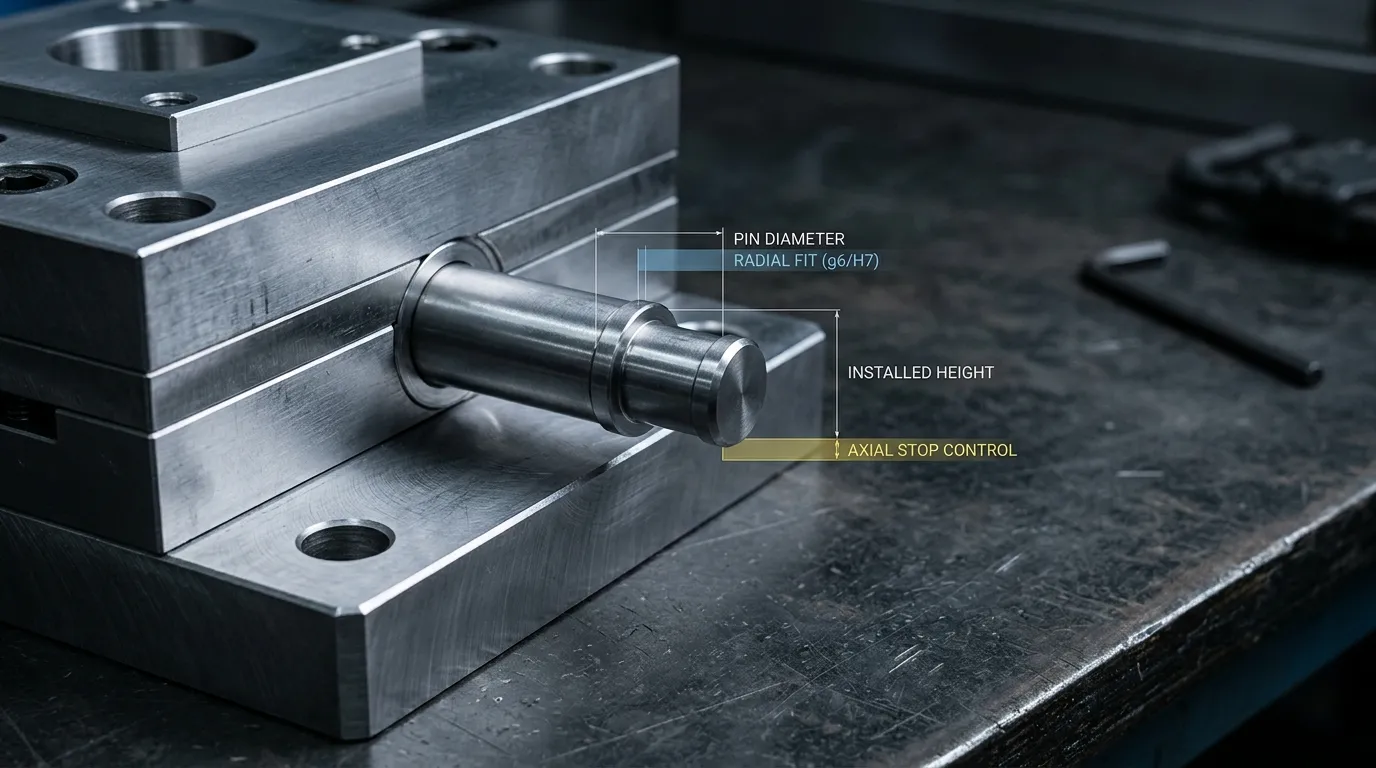
Mold limit pin tolerance and fit must control two different functions. The pin-to-bore fit controls retention, assembly force, location, and removability. The pin’s working height, seating geometry, surrounding plate dimensions, and contact faces control where the assembly actually stops.
A tight pin diameter alone does not guarantee repeatable stopping. The mating bore, seat depth, shoulder thickness, stop-face geometry, and complete axial tolerance stack must also be defined. Within the wider system of Molde de peças padrão (inferido), this makes the limit pin a component that must be specified from its installed function rather than from catalogue dimensions alone.
What Tolerance and Fit Actually Control in a Mold Limit Pin
The mounting fit and the stopping dimension solve different engineering problems.
Radial fit between the pin body and bore controls:
- How easily the pin can be assembled
- Whether it can move or rock inside the bore
- How much force is needed for installation
- Whether friction alone retains it
- How easily it can be removed during maintenance
- Whether excessive interference could damage the pin or plate
Axial dimensions and contact geometry control:
- The installed working height
- The final stopping position
- Whether several pins contact at the same time
- How contact load is distributed
- Whether the stop face sits squarely against the opposing surface
This distinction matters because a pin can be firmly retained while still producing an incorrect stop position. The opposite is also possible: the working height may be correct, but an excessively loose mounting fit can allow movement, fretting, or inconsistent contact.
Limit Pin, Stop Pin, Guide Pin, or Dowel—Why the Name Matters
Suppliers may use terms such as pino de limite de molde, pino de parada de molde, pino de travagem, stop button, or rest button for related stopping components. The name alone does not confirm the exact geometry or installed function.
A guide pin normally works with a bushing to control sliding alignment between mold sections. A dowel pin locates stationary components relative to each other. A return pin and an ejector pin perform separate functions within the ejector system.
The assembly drawing should therefore confirm what movement the component limits, which surfaces contact, and how it is retained. For a broader explanation of sliding alignment components, see mold pins and bushings.
Map Each Critical Dimension to Its Function
A useful limit pin drawing should identify each critical feature according to what it controls.
| Característica | Mating Feature | Função principal | Typical Inspection Focus |
|---|---|---|---|
| Pin body outer diameter | Mounting bore | Radial fit, location, and possible frictional retention | Diameter at relevant positions and orientations |
| Mounting bore | Pin body | Clearance or interference range | Bore size, geometry, surface condition, and lead-in |
| Duração do engajamento | Bore length | Retention behavior and support against rocking | Effective contact length |
| Shoulder or head thickness | Plate seating surface | Axial location of the pin | Thickness and seating-face condition |
| Counterbore or seat depth | Pin shoulder or head | Installed working height | Depth from the functional datum |
| Functional working height | Opposing stop surface | Final stopping position | Height from the installed seating datum |
| Overall pin length | Assembly envelope | Packaging and clearance within the assembly | Overall dimension where functionally relevant |
| Stop-face diameter | Opposing plate or stop surface | Contact area and local pressure distribution | Diameter, flatness, wear, and damage |
| Stop-face position | Seating face and pin axis | Full and square contact | Parallelism or perpendicularity where required |
The pin body tolerance should never be reviewed in isolation. A nominal 10 mm pin, for example, does not reveal whether the assembly will have clearance or interference unless the accepted bore limits are also known.
Overall Length Is Not Always the Functional Stopping Dimension
The functional dimension is the distance from the surface that seats the pin to the surface that makes the stop contact.
For a headed or shouldered pin, this may differ from the pin’s full end-to-end length. For a counterbored installation, the seat depth also changes the installed projection. A screw-retained stop button may use another surface as its axial reference.
The drawing should dimension the working height directly from defined functional datums whenever possible. Controlling only the overall length can leave the true stopping dimension dependent on several uncontrolled intermediate features.
How to Choose Clearance, Transition, or Interference Fit
There is no universal fit class for every mold limit pin. The appropriate choice depends on how the pin is retained, whether it must be replaceable, the mating materials, engagement length, temperature, available installation force, and expected contact conditions.
O ISO 286 tolerance system provides a standardized framework for expressing hole and shaft tolerance zones. It does not prescribe one fit for all mold stop applications.
| Tipo de Ajuste | Principal Vantagem | Limitação Principal | Appropriate Direction |
| Ajuste de folga | Easy assembly and removal | Does not provide frictional retention; movement may occur without another locating or retaining feature | Use when serviceability is important and retention is provided separately |
| Transition fit | Can provide close location with low clearance or light interference | Actual assemblies may vary between clearance and interference | Use when controlled location is needed but heavy pressing is undesirable |
| Ajuste por interferência | Provides frictional retention and limits radial movement | Higher installation force, possible bore stress, difficult removal, and risk of plate damage | Use only after checking material, engagement length, assembly method, and maintenance needs |
| Mechanically retained fit | Retention comes from a shoulder, screw, head, thread, or other positive feature | Requires additional geometry and access | Useful when the designer wants controlled location with predictable removal |
A stronger interference fit is not automatically better. Excessive interference can increase assembly force, scrape surfaces, distort a thin surrounding section, or make replacement difficult. Too little retention can allow the pin to shift or fret inside the bore.
The design decision should answer five questions:
- Must the pin be removable without remachining the plate?
- Is radial location provided by the body fit or by another feature?
- Does friction retain the pin, or is there a shoulder, head, screw, or thread?
- What engagement length and plate material surround the pin?
- Can the specified fit be assembled and inspected consistently?
Calculate the Worst-Case Assembled Fit
Use the actual accepted limits of the pin and bore, not only their nominal sizes.
Let:
- (H_{max}) = largest accepted bore
- (H_{min}) = smallest accepted bore
- (P_{max}) = largest accepted pin
- (P_{min}) = smallest accepted pin
Então:
Maximum clearance
[
C_{max} = H_{max} - P_{min}
]
Minimum clearance
[
C_{min} = H_{min} - P_{max}
]
A positive result indicates clearance. A negative result indicates interference.
For example, suppose a hypothetical design allows a bore from 10.000 to 10.012 mm and a pin from 9.996 to 10.004 mm.
- Maximum clearance = 10.012 − 9.996 = 0.016 mm
- Minimum clearance = 10.000 − 10.004 = −0.004 mm
This is a transition condition because accepted parts could assemble with either clearance or interference. The designer must confirm that both extremes are acceptable.
When Removability Matters More Than Maximum Retention
A limit pin may become a service item if its contact face wears, the mold is rebuilt, or the stopping position must be adjusted. A heavy press fit can make replacement more difficult and may damage the mounting bore during removal.
Where serviceability matters, a controlled clearance or transition fit combined with positive retention may be more practical than relying only on interference. The correct choice depends on the assembly layout and should be established before the pin and bore tolerances are finalized.
Build the Axial Tolerance Stack for the Stopping Position
The final stopping position is the result of every dimension between the fixed seating datum and the moving contact surface. Tightening the pin-length tolerance cannot compensate for an uncontrolled seat or plate stack.
A practical stack analysis follows this sequence:
- Identify the fixed functional datum.
This may be the backing plate surface, counterbore floor, shoulder seat, or another stable reference. - Identify the final contact surface.
Define exactly which pin face and opposing plate face establish the stop. - List every dimension in the datum chain.
Include the pin working height, shoulder thickness, counterbore depth, plate thickness, spacer thickness, and any other feature that changes the installed projection. - Assign direction to each dimension.
Some dimensions increase the projection; others reduce it. - Calculate the accepted extreme positions.
Use the maximum and minimum limits to determine the total possible stop-position range. - Compare the stack with the functional allowance.
If the stack is too wide, improve the dimensions that contribute most strongly rather than tightening every feature without reason.
A simplified symbolic stack could be written as:
[
S = W - D + T
]
Onde:
- (S) = installed stop position
- (W) = pin working height
- (D) = seat or counterbore depth
- (T) = any additional plate or spacer dimension in the functional chain
The actual equation must follow the real assembly configuration.
Define Working Height from Functional Datums
The working height should be measured from the surface that fully seats the component to the face that makes stop contact. Those surfaces should also guide the drawing datum system.
Direct functional dimensioning is usually clearer than a long chain of dimensions. If the stop position depends on the difference between overall length, head thickness, and seat depth, each tolerance contributes to the final variation.
O ASME Y14.5 dimensioning and tolerancing standard provides standardized rules for defining datums and geometric relationships on engineering drawings. The selected controls should reflect the actual stopping function rather than being added automatically.
Match Multiple Pins for Simultaneous Contact
Several limit pins with the same nominal length may not contact simultaneously. Relative working-height differences, seat-depth variation, plate flatness, and stop-face geometry can cause one pin to touch first.
The first pin to contact may receive a disproportionate share of the initial load. Typical evidence includes:
- A strong witness mark on one pin and little contact on the others
- Peening or indentation concentrated at one location
- Rocking or tilting as the moving plate reaches the stop
- Changing contact patterns after a replacement pin is installed
Where simultaneous contact matters, specify how closely the pins must be matched as a set. The assembly inspection should also verify the contact pattern rather than accepting each loose pin only by its individual length.
Control Geometry, Seating, and Surface Condition
Size tolerance alone does not ensure complete seating or square contact.
The following controls may be relevant:
- Stop-face flatness: Helps create consistent face contact.
- Parallelism: May be needed between the seating face and stop face.
- Perpendicularity: May relate the pin axis to a shoulder or contact face.
- Position: May be needed where pin location affects engagement with a specific contact area.
- Bore geometry: Roundness, straightness, and surface condition can affect assembly even when measured bore size appears acceptable.
- Surface finish: Influences friction during assembly, seating consistency, measurement, and contact behavior.
Burrs, debris, damaged counterbores, raised edges, or incomplete seating can change the installed height. A dimensionally correct pin may therefore produce the wrong stopping position after assembly.
Coating or surface-treatment thickness must also be considered when it changes the final pin diameter or working height. Dimensions should clearly apply to the correct manufacturing condition.
Use GD&T Only Where the Functional Relationship Requires It
Geometric dimensioning and tolerancing should protect a defined function.
For example:
- Apply flatness when the stop face must make controlled area contact.
- Apply parallelism when the stop face must remain parallel to the seating datum.
- Apply perpendicularity when the pin axis must remain square to a functional face.
- Apply position when the pin must contact a defined area or align with another assembly feature.
Avoid adding tight geometric controls without a measurement plan. A callout has little value when the supplier or inspection team cannot verify it reliably.
Inspect the Pin, Bore, and Installed Stop
Inspection should follow the functional chain rather than checking only the loose component.
- Clean the pin, bore, seating face, and measuring surfaces.
- Allow the parts and measuring equipment to stabilize.
- Measure the pin body at relevant positions and orientations.
- Verify the mating bore using a suitable bore gauge, pin gauge, or other controlled method.
- Check the shoulder or head thickness and seat depth.
- Measure the working height from the functional seating datum.
- Inspect specified stop-face and seating geometry.
- Assemble the pin and confirm complete seating.
- Measure the installed stop position or final plate position.
- Check contact patterns when several pins share the stop.
The measuring method must have sufficient resolution and controlled uncertainty for the specified tolerance. A narrow drawing tolerance cannot be accepted confidently with an instrument or process that cannot resolve the difference between conforming and nonconforming parts.
For broader supplier and quality considerations affecting Peças de molde de precisão, the inspection plan should still return to the specific limit-pin features that control the stop.
Control Temperature Before Accepting Close Measurements
Dimensional measurements are sensitive to temperature because the pin, plate, and measuring equipment expand or contract. Industrial dimensional measurements conventionally use 20°C as the reference temperature, as explained by the Instituto Nacional de Padrões e Tecnologia.
For close tolerances:
- Stabilize the pin and plate before measurement.
- Avoid measuring a warm part immediately after grinding or handling.
- Record temperature when it can materially affect the result.
- Include temperature-related uncertainty where required by the tolerance.
Inspect the Installed Assembly, Not Only the Loose Pin
Loose-part inspection confirms component dimensions. It does not prove that the assembled stop is correct.
After installation, verify:
- Full contact with the seating surface
- Installed working height
- Final stopped position of the moving plate
- Contact across every intended limit pin
- Absence of rocking or visible gaps
- No change caused by debris, burrs, or installation damage
Assembly-level inspection is especially important when the stopping position depends on several plates and seated features.
Diagnose Common Fit and Tolerance Failures
| Sintoma | Possible Cause | Inspection Check | Corrective Direction |
| Pin moves or rocks in the bore | Excessive clearance, bore wear, short engagement, or missing retention | Measure pin and bore limits; inspect engagement length and retention feature | Correct the fit or add suitable positive retention |
| Installation force is excessive | Too much interference, damaged lead-in, burrs, rough finish, or misalignment | Check actual interference and inspect bore entrance and surfaces | Correct the bore or fit specification; do not force assembly |
| Pin will not seat fully | Debris, burrs, damaged counterbore, incorrect shoulder geometry, or trapped obstruction | Inspect the seat and compare installed height with the drawing | Clean or repair the seating feature and verify geometry |
| Stop position varies after replacement | Replacement working height differs, seat damage, or tolerance stack was not controlled | Compare functional working heights and inspect the seat | Specify interchangeable working height from functional datums |
| One pin shows heavy witness marks | Unequal pin heights, seat-depth variation, plate distortion, or poor parallelism | Check matched heights and contact patterns | Correct the relative stack or contact geometry |
| Peening or indentation appears on the stop face | Concentrated contact, insufficient area, excessive impact, or unsuitable material pairing | Inspect contact area, surface geometry, hardness condition, and load distribution | Review the contact design and material condition |
| Bore shows fretting or polishing | Micromovement under load | Inspect fit, retention, and signs of cyclic movement | Improve location or retention after checking serviceability needs |
| Plate is damaged during removal | Excessive interference or inadequate removal access | Compare actual fit with the maintenance requirement | Use a more serviceable retention strategy in future designs |
Replacement should be based on condition, dimensional change, contact damage, or loss of function—not a universal cycle count.
Turn the Functional Requirement into a Drawing or RFQ
A useful RFQ should include the mating assembly, not only a standalone pin sketch.
Ofereça:
- Pin nominal diameter and accepted limits
- Mating-bore nominal diameter and accepted limits
- Required fit or acceptable clearance/interference range
- Functional working height and reference datums
- Overall length where separately relevant
- Shoulder, head, thread, screw, or retention details
- Effective engagement length
- Plate materials and relevant heat-treatment condition
- Stop-face diameter and required geometric controls
- Seat or counterbore dimensions
- Surface-finish or coating requirements where functional
- Quantity and whether pins must be matched as a set
- Spare-part interchangeability requirements
- Required material, hardness, and dimensional reports
- Assembly drawing or section showing the stopping function
The supplier should also know whether the component must be removable and whether final dimensions apply before or after heat treatment or coating.
What SunshinePro’s Published Tolerances Can—and Cannot—Tell You
SunshinePro's Página do produto Mold Limit Pin, lists S45C material, an outer-diameter tolerance of −0.01 to −0.2 with precision grinding, a length tolerance of +0.1 to +0.5, and product hardness of 15–17 HRC. The page also states that standard sizes and non-standard size customization are available.
These published values describe the listed product, but they do not independently define:
- The resulting pin-to-bore fit
- The permitted clearance or interference
- The functional working-height tolerance
- The seat and plate tolerance stack
- The required contact geometry
- The suitability of the component for a specific load or maintenance plan
A complete inquiry should therefore include the mating bore, functional datums, installed working height, retention method, and assembly context. SunshinePro describes a workflow that includes drawing submission, design review, quotation, processing, and quality inspection.
Once those requirements are defined, you can submit the limit pin and mating-assembly drawing for review or quotation. This gives the supplier enough information to evaluate the complete stopping function rather than matching only a pin diameter and overall length.
Compartilhar:


Escrito por Tonmoy
NOTÍCIAS
RECEBA O SERVIÇO
Com peças de qualidade para todos os orçamentos e equipe amigável treinada para tornar sua visita informativa e sem complicações.
