



Medição do Desgaste do Cilindro do Chip de Tablet e Limites de Inspeção
Tablet die bore wear measurement requires more than checking the internal surface for a visible ring. A wear ring can identify a suspect area, but it cannot show how much the bore has enlarged, whether the change is uniform, or whether the die remains within an approved operating limit.
A reliable inspection combines visual examination with controlled dimensional measurements at defined depths and orientations. The results should be compared with the correct tooling drawing, setting reference, or new-tool baseline. Acceptable wear must then be judged against product-specific warning and rejection limits—not a universal value taken from another tooling set.
For broader context on how dies interact with upper and lower punches, Veja Tipos de ferramentas para press de tablets. This guide focuses specifically on measuring internal die-bore condition and deciding what to do with the result.
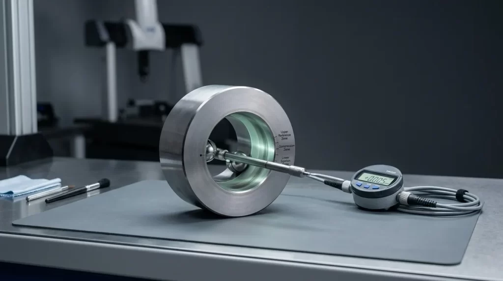
Como é o desgaste do diâmetro do tablet e por que isso importa
A tablet die bore can experience both dimensional wear and surface deterioration. Dimensional wear changes the bore profile or size. Surface deterioration includes scoring, Pitting, Corrosão, or roughness that may increase friction even when the diameter has not changed significantly.
A wear ring often develops around the working or compression zone. It may appear as a polished band, a change in reflection, or a visible transition on the internal surface. Its presence should trigger dimensional inspection, but it does not establish a pass or fail result.
Bore enlargement changes the functional clearance between the die and the punch tip. When that clearance becomes excessive or uneven, it can contribute to:
- powder leakage between the punch tip and die wall;
- thin fins or flashing around the tablet edge;
- accelerated punch-tip wear;
- poor tablet-edge definition;
- increased friction or inconsistent ejection;
- unstable performance across tools in the same set.
These symptoms are not proof of die wear. Formulation behavior, Lubrificação, Configurações de compressão, tool alignment, Contaminação, and punch condition can produce similar problems. They should be treated as inspection triggers.
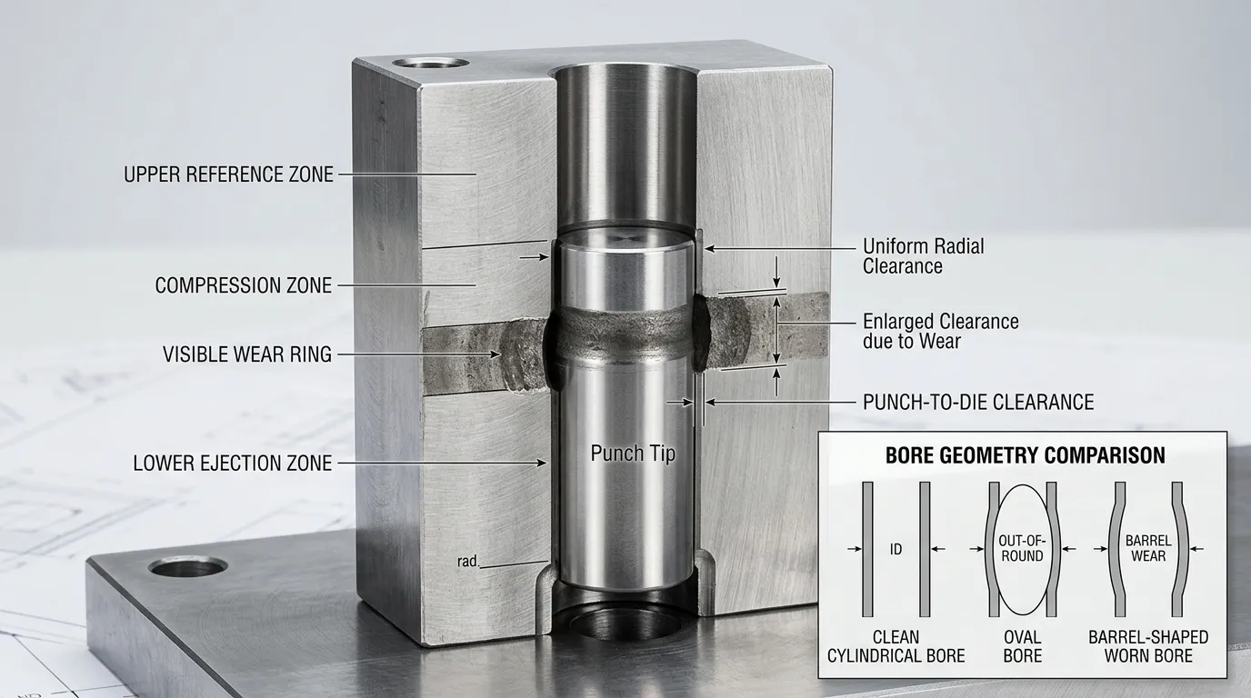
Wear, Residue, Pontuação, Afunilamento, or Geometric Distortion?
Several bore conditions can resemble wear or produce misleading measurements.
| Condição | Indicação típica | Como confirmar |
|---|---|---|
| Resíduo de produto ou filmagem | Patchy deposit, sticky surface, unstable readings | Clean the bore using the approved procedure, then measure again |
| Anel de desgaste | Faixa localizada polida ou ampliada | Measure at several depths above, within, and below the suspected area |
| Pontuação de superfície | Riscos ou sulcos lineares | Inspecionar sob luz direcionada e avaliar os danos na superfície separadamente do diâmetro |
| Afunilamento intencional | Mudança dimensional gradual ao longo do tubo | Compare as medições com o desenho de ferramentas controladas |
| Ovalidade | Leituras diferentes em orientações diferentes | Meça em posições angulares consistentes ou eixos de perfil |
| Desgaste em formato de cano | Leitura maior no meio do que nas posições superior e inferior | Compare leituras em várias profundidades definidas |
| Erro de calibre ou de operador | Resultados inconsistentes na mesma posição | Recheck zero, Posição de contato, Limpeza, and measurement technique |
The tooling drawing is essential when a die includes intentional taper or a non-uniform profile. A designed dimensional transition must not be classified as service wear.
Ferramentas e Dados de Referência Necessários Antes da Medição
A practical tablet die-bore inspection setup normally includes:
- a suitable split-ball bore gauge or another qualified internal comparator;
- a mechanical or digital deviation indicator;
- the correct setting master or setting ring;
- the controlled tooling drawing and current revision;
- new-tool baseline readings, Quando disponível;
- directed lighting or a bore-inspection light;
- approved cleaning materials;
- an inspection record linked to the die or tooling-set ID;
- evidence that the instrument is within its calibration or verification period.
A split-ball bore gauge measures deviation relative to a reference rather than producing a complete geometric scan. The probe must match the bore range and profile being inspected. Original instrument documentation, such as the guidance for a Sonda de bola dividida e mestre de ajuste, should control the setup and handling method.
Calibration status alone does not prove that the measurement method is suitable for the decision. The instrument must also have enough resolution, Repetibilidade, and measurement capability for the inspection limit being applied. O Orientação do NIST sobre rastreabilidade metrológica distinguishes traceability from fitness for a specific measurement purpose.
Calibre de diâmetro de bola dividida versus medidor de plugue
| Método de inspeção | Uso principal | Limitação |
| Bitola de bola dividida | Mede o desvio comparativo em profundidades e orientações selecionadas | Requires correct zeroing, Alinhamento, contact selection, e técnica do operador |
| Mostrador fixo de vela | Confirma se um tamanho de bitola fixo pode entrar em um diâmetro | Não quantifica o aumento localizado ou o desgaste do mapa por profundidade |
| Inspeção óptica ou coordenada | Pode avaliar perfis complexos quando configurado corretamente | May require specialist equipment, Fixação, Software, and validated access to internal features |
A plug gauge can support a pass/fail check for a defined size, but it is not a complete substitute for localized wear measurement.
Desenho, Nominal Size, and New-Tool Baseline
Before measuring, confirmar:
- the correct die or tooling-set ID;
- the correct drawing revision;
- the nominal bore profile and units;
- whether the die has an intentional taper;
- the reference positions used for dimensional control;
- any measurements recorded when the die was new.
The nominal drawing dimension defines the intended design, while a new-tool baseline records the actual starting condition at controlled locations. Keeping both makes later wear trending more reliable.
Como medir o desgaste do diâmetro do die de tablets
The approved site procedure and the gauge manufacturer’s instructions should take priority over a general guide. The sequence below shows the controls that a repeatable inspection process should contain.
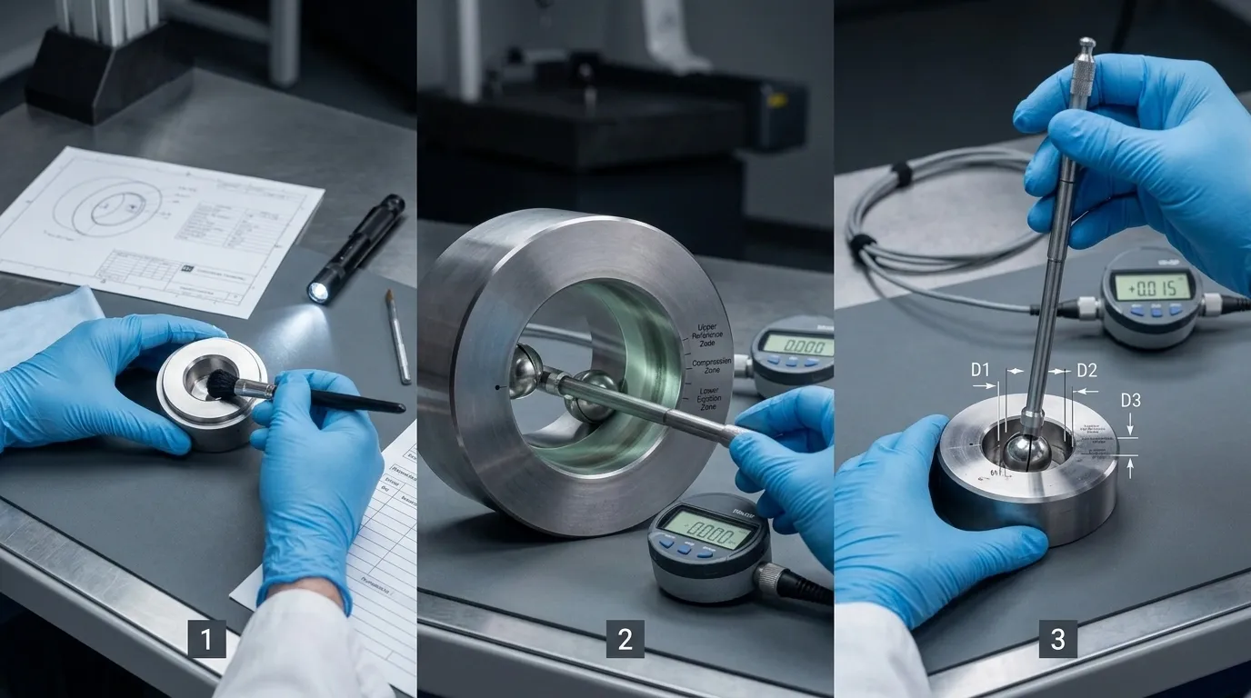
Step 1 — Identify, Limpo, and Visually Inspect the Die
Record the die ID before cleaning or measuring. Confirm the drawing revision and previous inspection status.
Clean the bore thoroughly using the approved method. Product residue, polishing compound, lubrificante, or corrosion products can alter the contact between the gauge and bore wall.
Inspect the full internal surface under directed light. Record visible conditions such as:
- a polished or enlarged wear ring;
- scoring or scratches;
- pitting or corrosion;
- rachaduras, chips, or edge damage;
- residue that remains after cleaning;
- a visible taper transition;
- localized discoloration or roughness.
Photographs can help preserve evidence when unusual damage is found. Para operações farmacêuticas reguladas, written cleaning, Manutenção, and inspection procedures should follow applicable requirements such as 21 CFR 211.67.
Passo 2 — Definir e Verificar a Referência de Bitola
Select the correct gauge range and contact configuration for the bore.
Clean and inspect the setting master. Place the probe in the master according to the instrument instructions, then align or rock it as required to locate the correct comparative point. Set the indicator to zero or to the documented reference value.
Record the gauge and indicator identification. After the complete measurement series, return to the setting master and verify that the reference has not shifted. A changed zero may indicate drift, Contaminação, loose setup, or handling error.
Passo 3 — Meça um cunho redondo em profundidades e orientações definidas
Do not rely on a single reading near the bore entrance. Localized wear may exist only in the compression or ejection region.
Define repeatable measurement positions from the tooling drawing and inspection procedure. A typical measurement map may include:
| Região de medição | Propósito |
| Zona de referência superior | Estabelece a condição acima da área principal de trabalho |
| Zona de compressão ou anel de desgaste | Detecta aumento localizado onde a pastilha se forma |
| Zona inferior ou de ejeção | Verifica a região que influencia a liberação de tablets |
| Posições adicionais de transição | Confirms taper, barrel shape, or local damage |
At each depth:
- place the probe without dragging or forcing it against the bore;
- align it according to the approved technique;
- record the comparative reading;
- repeat the reading to check consistency;
- measure at additional orientations where required;
- record the maximum, minimum, and repeated values.
Different readings by depth can indicate localized or barrel-shaped wear. Different readings at the same depth but different orientations may indicate ovality or directional damage.
The exact depths should come from the die geometry and inspection SOP. One universal set of depth values cannot suit every die design.
Passo 4 — Meça matrizes oblongas e moldadas por perfil
An oblong or shaped die cannot be represented by one diameter reading.
Use the drawing to identify:
- the major axis;
- the minor axis;
- critical radii or profile transitions;
- orientation references;
- measurement locations at each required depth.
Record every result with both its depth and profile orientation. Suitable contacts or a different inspection system may be needed for complex shapes. If the available gauge cannot contact the required surfaces consistently, do not force a result. Escalate the inspection to the tooling supplier or a qualified metrology process.
| Os perfis | Abordagem de medição mínima |
| Rodada | Profundidades múltiplas e orientações angulares consistentes |
| Oval ou oblongo | Major axis, minor axis, and repeated depths |
| Perfil complexo | Drawing-defined contact points, raios, axes, and specialist method where required |
Step 5 — Repeat, Record, and Confirm the Measurement Series
Repeat any unstable reading. If repeated values differ beyond the approved measurement-system capability, check:
- bore cleanliness;
- probe contact position;
- gauge alignment;
- indicator mounting;
- setting-master cleanliness;
- zero stability;
- contact wear or damage;
- Técnica do operador.
The inspection record should contain more than a pass/fail result. Useful fields include:
- die or tooling-set ID;
- drawing number and revision;
- nominal profile;
- measurement depth;
- orientation or axis;
- repeated readings;
- maximum and minimum deviation;
- visual observations;
- instrument ID;
- setting-master ID;
- inspector and date;
- warning, rejection, or monitoring status;
- final disposition.
Recheck the setting master after the measurement series. If the reference has shifted, investigate and repeat affected readings.
Como Estabelecer Limites de Inspeção do Cilindro do Placão
There is no reliable universal wear limit for every tablet die.
A numerical example from another manufacturer, Produto, or tooling set may be inappropriate because the acceptable bore condition depends on:
- punch-tip and die geometry;
- original tooling tolerances;
- tablet shape and edge requirements;
- formulation behavior and abrasiveness;
- powder leakage or flashing sensitivity;
- Desempenho de ejeção;
- press condition and alignment;
- measurement-system capability;
- validated process and product history.
Orientações do setor sobre Monitoramento do desgaste do punção e matriz also treats acceptable deviation as product-dependent.
A new-tool manufacturing tolerance is not automatically the same as an in-service rejection limit. The first controls how the tool is produced. The second determines whether a used die still supports acceptable production.
Entradas para Limites de Aviso e Rejeição
Use controlled evidence to establish two separate levels where appropriate:
- Warning limit: triggers investigation, shorter reinspection intervals, or increased process monitoring.
- Rejection limit: triggers quarantine, removal from service, ou substituição.
The decision should consider:
| Entrada | Por que isso importa |
| Desenho de ferramentas | Defines the intended profile, Afunilamento, and original dimensional requirements |
| Linha de base para novas ferramentas | Mostra as leituras iniciais reais em posições controladas |
| Condição da ponta do punto | Ajuda a avaliar a folga funcional do punch-to-die |
| Borda de tablete e qualidade dimensional | Mostra se as ferramentas ainda produzem tablets aceitáveis |
| Histórico de impermeabilização ou vazamento de pólvora | Pode indicar aumento da depuração funcional |
| Tendência da força de ejeção | May reveal friction, Preparação, rugosidade, or wear requiring investigation |
| Histórico de formulação e execução | Ajuda a explicar as diferenças na taxa de desgaste |
| Repetibilidade e incerteza da medição | Determina a confiança em leituras próximas ao limite de ação |
| Recomendações de fornecedores | Adiciona orientações específicas de projeto quando suportado pelas ferramentas exatas |
| Validação do local e controle de alterações | Conecta o limite ao desempenho aprovado do produto e do processo |
The limit should be written into the inspection SOP with the reference data, measurement positions, required repetitions, Responsabilidades, and disposition rules.
Como Lidar com Resultados Borderline
A reading close to the action limit should not receive an automatic pass or fail when measurement uncertainty could change the decision.
Use a controlled confirmation process:
- clean the bore and setting master again;
- verify the gauge zero;
- repeat the measurement;
- use a second qualified operator if required;
- compare the result with nearby depths and orientations;
- review recent tablet-quality and process data;
- confirm with a more capable measurement method when necessary;
- quarantine the die until the result is resolved;
- document the final decision.
Como Interpretar os Resultados e Escolher a Próxima Ação
| Constatação da inspeção | Ação recomendada |
| Leitura instável ou contaminação visível | Limpo, verify zero, and remeasure |
| Resultado estável dentro do limite aprovado e sem danos inaceitáveis | Retorno ao serviço e manutenção do registro |
| Resultado próximo do limite de aviso | Reduzir o intervalo de reinspeção e revisar as tendências do processo |
| Resultado próximo ao limite relativo à incerteza da medição | Faça quarentena e confirme com um método qualificado |
| Limite de rejeição ultrapassado | Remova o die do serviço |
| Severe scoring, rachaduras, Lascamento, or unsafe damage | Quarentena independentemente do resultado do diâmetro |
| Requisito de desenho ou perfil incerto | Solicite revisão de fornecedor ou engenharia |
| Desgaste repetido em múltiplas ferramentas | Review punch condition, Alinhamento, Material, Formulação, e condições de operação |
Do not assume that dimensional enlargement is the only rejection reason. Surface damage can make a die unsuitable even when its measured diameter remains within the dimensional limit.
Processe Sintomas que Devem Desencadear uma Inspeção Não Programada
An unscheduled die-bore inspection may be justified when production shows:
- rising or unstable ejection force;
- difficult tablet release;
- new flashing or powder leakage;
- unusual punch-tip scoring;
- binding or increased friction;
- a change in tablet-edge definition;
- recurring chipping, Finalização, or lamination;
- inconsistent performance among stations using the same tooling set.
Desgastado, rough, scratched, or contaminated die surfaces can affect ejection friction, but ejection force also depends on formulation, Lubrificação, tablet geometry, e condições de compressão. The relationship is explained in this technical overview of Força de ejeção na compressão de comprimidos.
These symptoms should trigger investigation, not an immediate conclusion that the die bore is worn.
Erros comuns na medição do diário de tabletes
| Erro | Possível efeito | Prevenção |
| Medindo um diâmetro contaminado | Aumento falso ou leituras instáveis | Limpe e inspecione visualmente primeiro |
| Usando o alcance ou contato errado da sonda | Contato ruim ou valores enganosos | Ajuste a bitola ao cano e ao perfil |
| Pulando a verificação do mestre de configuração | Referência incorreta | Verifique antes e depois da série |
| Medindo em profundidades inconsistentes | Os resultados não podem ser comparados ao longo do tempo | Use posições definidas pelo desenho |
| Ignorando a orientação | Desgaste de ovalidade ou direcional pode ser ignorado | Gravar eixos ou posições angulares |
| Fazendo apenas uma leitura | Erro do operador pode passar despercebido | Medições repetidas |
| Inclinação ou balanço excessivo | Valores máximos ou mínimos artificiais | Siga a técnica de calibre qualificado |
| Usando a revisão errada do desenho | Geometria projetada pode ser classificada como desgaste | Confirme o controle do documento antes da inspeção |
| Ignorando o desmame intencional | Variações normais de projeto podem parecer defeituosas | Compare todos os resultados com o desenho |
| Confiando apenas no status de calibração | O método pode não ter resolução ou repetibilidade adequadas | Confirmar a capacidade de medição em relação ao limite de inspeção |
| Gravando apenas aprovação ou reprovação | Tendências de moda se perdem | Manter valores brutos e localizações |
Frequência de Inspeção, Records, and Wear Trending
Measure new tooling before production use where practical. This creates a baseline for later comparisons.
Depois disso, inspection frequency should reflect:
- tooling usage;
- Abrasividade da formulação;
- previous wear rate;
- product-quality risk;
- process symptoms;
- proximity to the warning limit;
- maintenance or cleaning events;
- the site’s validated procedure.
A fixed calendar interval may be insufficient. A die approaching its warning limit may require shorter intervals, while stable tooling with a documented history may follow the approved routine schedule.
Trend the actual readings by die ID, Profundidade, Orientação, and date. This allows the toolroom to see whether wear is stable, accelerating, or isolated to one region.
Die-bore measurement is only one part of a complete tooling inspection program. Punch dimensions require separate controls; Veja Inspeção do comprimento de trabalho do perfurador de tablets for that adjacent procedure.
For applicable pharmaceutical operations, routine calibration, Inspeção, checking, and records for mechanical or electronic equipment should follow written programs such as those described in 21 CFR 211.68.
Quando Envolver o Fornecedor de Ferramentas
Supplier or specialist review is appropriate when:
- the original drawing is unavailable;
- the baseline condition was never recorded;
- intentional taper or profile geometry is unclear;
- a shaped bore cannot be measured reliably with the available equipment;
- borderline results remain unresolved;
- repeated wear suggests a wider tooling or process issue;
- a replacement die must match an existing tool set.
Provide enough information for a meaningful review:
- tooling and die identification;
- drawing and revision, Se disponível;
- tablet and die profile;
- measurement depths and orientations;
- raw inspection readings;
- photographs of wear or damage;
- punch-tip condition;
- production symptoms;
- the required replacement or review objective.
Listas SunshinePro Ferramentas personalizadas para prensa de tablets, including punches and dies, and states that custom processing can be based on drawings or samples. When measured wear has reached the approved rejection point or the original profile requires review, the practical next step is to submit the available drawing, Exemplo, and inspection findings for a replacement-tooling discussion.
Compartilhe:


Escrito por Sunshine
Em Sol, Somos um fabricante e fornecedor profissional de componentes de moldes de precisão, oferecendo uma ampla variedade de produtos para aplicações de estampagem e molde por injeção. Nosso foco principal inclui a formação de matrizes, pinos e mangas ejetor, e postes guia e buchas. Com usinagem CNC avançada, Controle rigoroso de qualidade, e fortes capacidades de produção, Garantimos confiabilidade, Peças de alta precisão, juntamente com componentes padrão em estoque para fornecimento global rápido e eficiente.
NOTÍCIAS
RECEBA O SERVIÇO
Com peças de qualidade para todos os orçamentos e equipe amigável treinada para tornar sua visita informativa e sem complicações.
